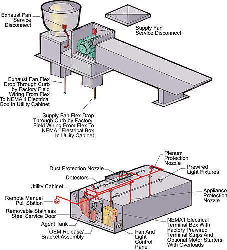
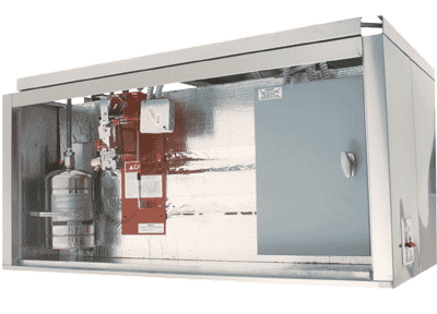
| AquaMatic's System 1-2-3 is comprised of a utility cabinet, a
pre-piped fire protection system and a pre-wired fan and light
electrical control panel. Both fire protection and electrical
control components are contained in the utility cabinet.
|
|
|
|
|
The utility cabinet is UL Listed for integral left or right side mount on
the AquaMatic ventilation hood. It is welded directly to the hood and
abricated of the same material as the hood. To conceal fire extinguishing
and wiring apparatus, the fire cabinet is equipped with a full length,
removable door with a center handle. UL tests confirm temperatures do
not exceed 120°F inside the cabinet during a fire condition. (120°F is the
maximum allowed storage temperature for the UL Listed fire suppression
system and the UL Listed industrial control panel.)
|
|
|
|
|
The fire extinguishing system is a pre-engineered distribution network. The
extinguishing agent is a low pH liquid, non-corrosive type. The system is capable
of automatic detection and activation or manual activation through a remote manual
pull station. It is Listed with Underwriters Laboratories, Inc. The tank(s) can be
contained in the AquqMatic UL Listed utility cabinet. The cabinet is fabricated
with a full length, removable door and center handle and is an integral part of
the canopy. The system is completely factory pre-piped by trained personnel in
accordance with UL 300, NFPA #96, #17 and #17A. Each exposed fitting is chrome
plated. Exposed piping is covered with heavy gauge stainless steel sleeving. System
is capable of fuel shut down upon discharge. A mechanical or electrical gas valve
can be provided. A microswitch is provided for connection to the pre-wire package
for the automatic shut down of supply air fans in the event of system discharge.
Field hookup and testing will be subcontracted by AquaMatic to a qualified and
insured fire distributor and will be performed after hood installation. A CAD
generated drawing will be custom produced for each installation, indicating all
drop locations and piping schematic in accordance with local requirements. As
provided under Section 16, electrical wiring requirements are provided by the
jobsite Electrical Contractor.
Inspections and routine maintenance at the specified 6-month intervals shall
become the responsibility of the customer. The basic fire system components
shall include:
- Release Assembly: Actuates extinguishing system,
shuts down cooking equipment, supply fan and fuel supplies.
- Agent Tank: Contains the special liquid fire
extinguishing agent.
- Detectors: Fusible link spaced throughout
hood(s) to activate the automan in case of fire.
- Nozzles: Placed throughout the hood(s)
according to cooking equipment and system guidelines, the nozzles direct
the extinguishing agent onto the fire hazard areas such as the duct, plenum
and cooking equipment.
- Pull Station: Mounts near the kitchen exit
and allows manual activation of fire system.
|
|
|
|
The control panels, three phase or single phase, are available in various
sizes depending on the number of fans controlled by the panel. The control
panel and the control switching have two mounting options:
- Inside Hood's UL Listed Utility Cabinet with
switches face mounted on the utility cabinet.
- Inside Stainless Steel Box, wall mounted
(recessed or surface mounted) with switches mounted on the face of the
stainless steel box. (All control connections must be field wired with this option.)
- Inside NEMA-1 Box (gray) with switches mounted on
hood or shipped loose. (All control connections must be field wired with this option.)
All control panels are thoroughly tested before leaving the factory. For most
applications, the electrical control panels are UL Listed.
Field Wiring Requirements:
- Motor power, single or three phase, to the control panel.
- Motor wire from the control panel to the fans.
- Power to the control panel for the lights.
- Control panel circuit power.
- Wiring from the control panel to the lights, and fire system microswitch
(if the control panel is wall mounted).
Single Phase Control Panels:
- The maximum horse power for a 120V is 1 1/2 HP; the maximum horse power
for a 220V is 2 HP. The minimum NEMA control box dimensions
are 8" x 8" x 4", with 1/2" and 3/4" knockouts.
Three Phase Control Panels:
- The minimum NEMA control box dimensions are 12" x 18" x 6", with
1 1/2" and 3/4" knockouts. The motor overloads are factory set to the
size of the motors ordered for the system. The contactor and overload
combination (Starter) are DIN rail mounted.
|
|
|
|
- UL Listed Utility Cabinet Welded directly on end of hood to conceal fire
system and electrical apparatus
- UL Listed Pre-Piped Fire Extinguishing System Minimizes field installation
requirements. Field certification subcontracted by AquaMatic, eliminating all
fire system installation related costs to customer.
- UL Listed Pre-Wired Electrical Minimizes cost and complexity of field
wiring requirements.
- Control Panel with Color Coded Wiring
- Numbered Terminal Blocks
- Grounding Bar
- Spare Terminals Controlled by Fire System Microswitch
- Factory Pre-Wired to Shut Down Fans During Fire Condition
- Illuminated Pilot Lighted Fan Switch; Enclosed in Flexible Conduit or EMT
- Wiring Diagram
- Relays and/or Starters
|
|
|
|
|
AquaMatic® offers a total system to insure maximum installation and operating
efficiencies. Components consist of the ventilator, fire system and electrical
controls contained within an integral utility cabinet, and fan packages including
exhaust, untempered and tempered make-up air packages. Also available are air
purification and energy management systems. Fire suppression systems include
final hookup and inspection. Call your AquaMatic Representative for more details.
|
|
|
|

|


