
This site is protected by reCAPTCHA and the Google Privacy Policy and Terms of Service apply.
- Digital Interface with LCD Screen
- Customizable Options via Microprocessor Control
- Plug and Play Wiring between Digital Interface and Equipment
- Reduces High Voltage Wiring between Devices
- Alarm notifications displayed in English text to improve installation quality
- Automatic Fan Operation - meets IMC Code 507.2.1.1
- Integrated Reset for Electric Gas Valves
- Monitoring of Fan Overload Trips
 Standard LCD Screen with Optional Demand Ventilation Upgrade
Demand Control Ventilation (DCV)
- Automatically modulates fans based on cooking load. Modulation allows for energy savings compared to fans running on high speed during cooking operation.
- Max Airflow Override and real-time energy savings displayed
- Preparation Time Function: Exhaust fans will automatically turn on at low CFM and lock-out dedicated make-up air. Designed for morning operation when light food preparation is being performed.
- Cool Down Function: At the end of cooking operations, the exhaust fans will automatically turn down to a low CFM and lock-out dedicated make-up air. Designed for equipment cool-down period at the end of the night.
- Wiring between VFDs and Control Board is simplified with the use of CAT-5
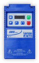
 VFDs - Variable Frequency Drives
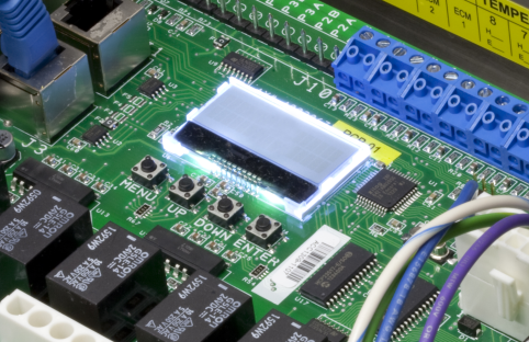
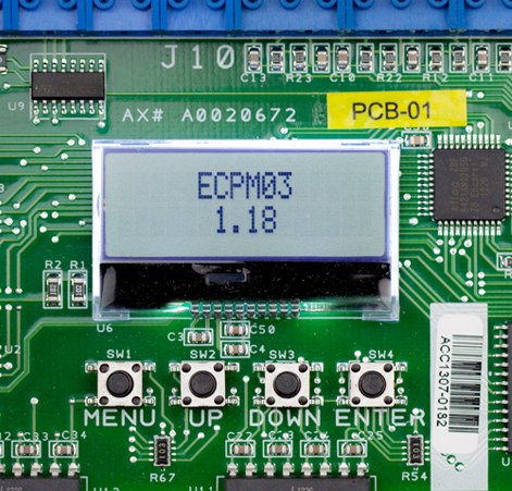
Microprocessor-Based System Controller
VFDs - Variable Frequency Drives
Microprocessor-Based System Controllerand LCD Screen Interface
Advanced Digital Logic Controller &
LCD Based Option Configuration
- Allows for system flexibility and easy adjustment
- Need to update a feature to meet local code? Simply activate the option via the LCD screen. No field rewiring needed.
- Functionality to meet National and Local Codes built-in by default
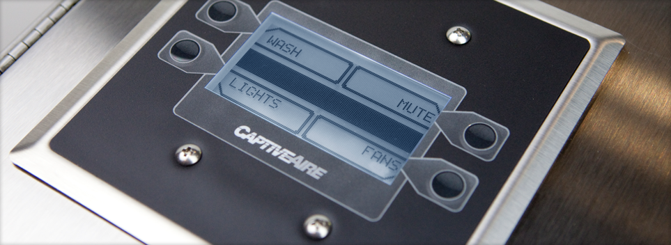
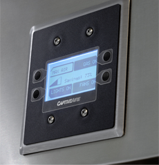
System Controller
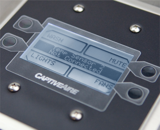
LCD Based User Interface
- Real-time status of fans, lights and electric gas valve
- Provides audible alerts of failures or issues
- Alarm notifications displayed in English text to improve installation quality
- Robust screen to withstand commercial kitchen environment
- Display of overload status for fan zone. If the overload trips, an alert notifies the operator immediately
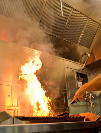
Automatic Fan Activation
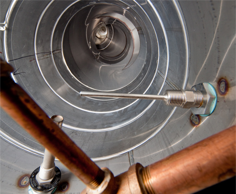
- How it works: If the exhaust duct sensor detects a temperature rise of a fixed differential over kitchen space temperature, the fans will automatically turn on
- System can run in the automatic mode to save energy, respond to cooking appliances and meet code
- Improved response time versus traditional fixed temperature activation set point systems
Integrated Features
Integrated Electronic Gas Valve Reset Relay
- Built-in reset relay included for all packages
- External reset button and relay is no longer needed and installation is simplified
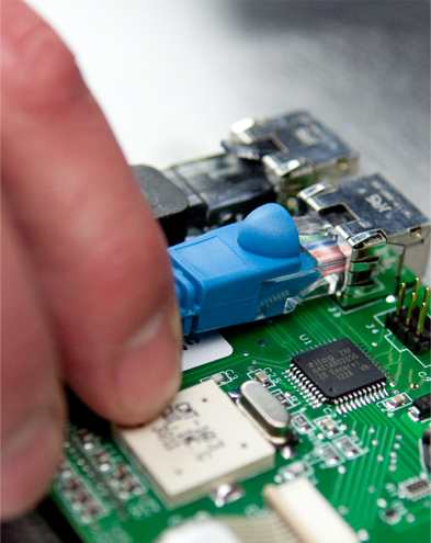
Plug & Play Switch Wiring
- Field wired switches are now wired using a single
CAT-5 cable - Low voltage wiring reduces installation cost
- Reduced high voltage wiring between devices
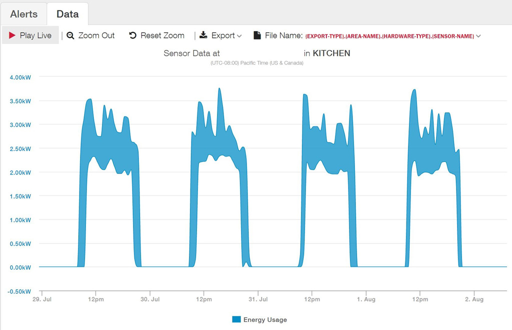
Remote Monitoring and Control
- Cloud-based monitoring of temperatures, fans, controllers, VFDs, energy usage, overloads and other faults where applicable
- Remote overrides, scheduling and settings changes based on historical operational data
- Email alerts for emergency conditions such as system faults and/or fans running during unoccupied times
- 24/7 real time fire system status when used in conjunction with CORE Fire Systems
CASLink Monitoring and Controls
Additional Information
- Thermostatic Control Sales Brochure
- DCV Sales Brochure
- Operation & Installation Manual
- Thermostatic Controls Written Specification
- DCV Written Specification (pdf)
- DCV Written Specification (docx)
- Hood Installation
- Duct Temperature Sensor Install Diagram (PDF)
- Duct Temperature Sensor Install Diagram (ACAD Drawing)
- Duct Sensor (Thermistor) Manufacturer Specification Sheet
- Room Sensor (Thermistor) Manufacturer Specification Sheet
- Temperature Interlock with Standard Switches
- SMV 571 VFD Manufacturer Operating Instructions
- Direct Digital Controls (DCV)

The Electrical Control Panel Model has been certified by ITS. This certification mark indicates that the product has been tested to and has met the minimum requirements of a widely recognized (consensus) U.S. and Canadian products safety standard, that the manufacturing site has been audited, and that the applicant has agreed to a program of periodic factory follow-up inspections to verify continued performance.
Models Electrical Control Panel are ETL Listed under file number 101754591COL-001 and complies with UL508A Standards and CAN/CSA C22.2, No. 14-05 Standards.
ECPM03 Circuit Board is ETL Listed under file number 100901773BOX-001 and complies with UL 61010-1 Standard and CAN/CSA C22.2, No. 61010-1 Standards.